Welcome to Hengli Transmission, we will serve you wholeheartedly!

Plum blossom coupling, star coupling, elastic pin coupling, cross slide coupling, coupling manufacturer, drum gear coupling_Hangzhou Hengli Transmission Equipment Co., Ltd.
 current position:
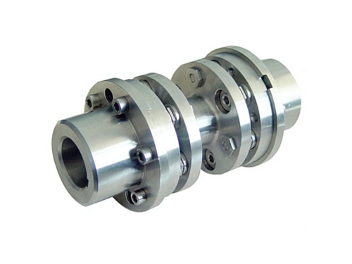
-
product name:
-
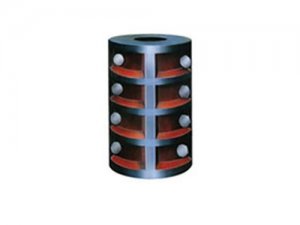
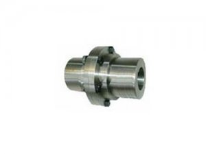
product description:The high-speed diaphragm coupling structure makes the left and right centers of gravity close to the support bearings of the units on both sides to the maximum extent, and the additional bending moment to the rotor shaft head..
-
Related tags:
Product Details
high speedDiaphragm couplingThe structure makes the left and right centers of gravity close to the support bearings of the units on both sides to the greatest extent, and the additional bending moment to the rotor shaft head is small, which is conducive to high-speed and stable operation.
The design of the high-speed diaphragm coupling should be able to operate continuously in the unit for more than 3 years, and the coupling and shaft connection should be able to withstand 175% of the large continuous torque during the operation of the unit; when transmitting 175% of the moment specified by the buyer The coupling does not break when torque is applied, but the connection is allowed to fail; when the displacement of the axis of the two shafts connected by the coupling reaches 125% of the rated value, it can operate normally and continuously.For couplings with spacer sleeves, the spacer sleeve should have sufficient length so that the coupling can be assembled and disassembled without moving the shaft.The coupling hub and shaft should adopt an interference fit.The size of the interference can be proposed by the buyer, but it must be agreed by the seller.
特点
The shaft hole types of high-speed diaphragm couplings include cylindrical holes with keys and conical holes; cylindrical holes without keys and conical holes for hydraulic assembly.The type of shaft hole is selected by the buyer.The tolerance level of cylindricity of shaft hole joint surface is 6.When measuring the cylindricity tolerance, it should be done before the keyway machining.Choice of interference between shaft hole and shaft (recommended value): cylindrical shaft hole with key, the interference is 0.5%-0.75% of the shaft diameter; conical shaft hole with key, the interference is 1% of the shaft diameter; for cylindrical holes without keys, the interference is 1.5%-1.8% of the shaft diameter; for hydraulically assembled conical shaft holes, the interference is 1.8%-2.0% of the shaft diameter.
| model | Allowable torque TN | Allowable speed n | Outer diameter A | Axle hole B | H | Shaft extension L | Axis spacing | R | Weight(kg) | |
| ×10 4 Nm | (rpm) | (Mm) | (Mm) | (Mm) | (Mm) | E Min(mm) | (Mm) | E min(mm) | 1000mm weight | |
| JNC1 | 0.1 | 35000 | 95 | 35 | 60 | 40 | 160 | 75 | 4.5 | 3.3 |
| JNC2 | 0.22 | 30000 | 122 | 50 | 75 | 55 | 170 | 90 | 6.5 | 4.13 |
| JNC3 | 0.34 | 26000 | 150 | 60 | 95 | 65 | 190 | 112 | 13 | 5.5 |
| JNC4 | 0.56 | 24000 | 170 | 65 | 105 | 70 | 210 | 122 | 19 | 6.14 |
| JNC5 | 0.95 | 22000 | 190 | 75 | 115 | 75 | 230 | 142 | 26 | 9.85 |
| JNC6 | 1.56 | 20000 | 210 | 85 | 130 | 85 | 230 | 165 | 34 | 12.7 |
| JNC7 | 2.4 | 17500 | 240 | 105 | 155 | 100 | 250 | 195 | 50 | 15.92 |
| JNC8 | 4.3 | 16000 | 280 | 125 | 175 | 120 | 260 | 218 | 72 | 22 |
| JNC9 | 4.72 | 13500 | 310 | 140 | 205 | 140 | 270 | 246 | 88 | 29.94 |
| JNC10 | 9.75 | 12000 | 340 | 150 | 220 | 150 | 290 | 270 | 136 | 38.28 |
| JNC11 | 12.5 | 11000 | 370 | 165 | 240 | 170 | 310 | 298 | 161 | 47.5 |
| JNC12 | 16.8 | 10000 | 400 | 180 | 260 | 180 | 320 | 321 | 205 | 55.6 |
| JNC13 | 21.3 | 9500 | 430 | 195 | 280 | 200 | 390 | 348 | 276 | 63.8 |
| JNC14 | 22.6 | 9000 | 460 | 205 | 295 | 210 | 400 | 368 | 326 | 75.6 |
| JNC15 | 28 | 8500 | 490 | 220 | 310 | 220 | 410 | 394 | 387 | 80.6 |
| JNC16 | 33 | 7700 | 516 | 235 | 330 | 235 | 450 | 418 | 468 | 86 |
| JNC17 | 36.6 | 7500 | 560 | 255 | 355 | 250 | 460 | 458 | 578 | 93.5 |
| JNC18 | 52 | 7000 | 600 | 280 | 380 | 290 | 480 | 485 | 660 | 142 |
- Previous:JMIJ type connecting intermediate shaft type diaphragm coupling
- Next:Nothing
Company News
News

-
 Coupling manufacturer's diaphragm coupling link device
How many sets of diaphragms (stainless steel thin plate) of the diaphragm coupling of the coupling manufacturer are interwoven with bolts...
Coupling manufacturer's diaphragm coupling link device
How many sets of diaphragms (stainless steel thin plate) of the diaphragm coupling of the coupling manufacturer are interwoven with bolts... Causes of coupling failures of coupling manufacturers
The characteristics of the sprocket coupling: the chain coupling has a simple structure, easy to assemble and disassemble, and there is no need to move when disassembling...
Causes of coupling failures of coupling manufacturers
The characteristics of the sprocket coupling: the chain coupling has a simple structure, easy to assemble and disassemble, and there is no need to move when disassembling... Shaft manufacturers analyze various types of coupling lubrication maintenance methods
Good lubrication of the coupling is to operate, it is a method to slow down the wear, and it is also an important way to improve the life of the coupling...
Shaft manufacturers analyze various types of coupling lubrication maintenance methods
Good lubrication of the coupling is to operate, it is a method to slow down the wear, and it is also an important way to improve the life of the coupling... Common failures of couplings
In the daily use of toothed couplings, the coupling manufacturer will show you that the following...
Common failures of couplings
In the daily use of toothed couplings, the coupling manufacturer will show you that the following... -
 Disassembly tool and maintenance of pin coupling
The pin coupling is used to drive the starter gearbox, starter generator and exciter.Pin coupling...
Disassembly tool and maintenance of pin coupling
The pin coupling is used to drive the starter gearbox, starter generator and exciter.Pin coupling... Technical advantages of flexible diaphragm coupling
1. Dry couplings, non-lubricated flexible diaphragm couplings rely on metal diaphragms to transmit torque and absorb...
Technical advantages of flexible diaphragm coupling
1. Dry couplings, non-lubricated flexible diaphragm couplings rely on metal diaphragms to transmit torque and absorb... Coupling requirements and optimized design structure
The torque transmission of the coupling is mainly to set the nominal torque requirement of the transmission system.When the torque transmission element...
Coupling requirements and optimized design structure
The torque transmission of the coupling is mainly to set the nominal torque requirement of the transmission system.When the torque transmission element... Advantages of universal coupling
What are the advantages of universal couplings and how to choose universal couplings?Coupling manufacturer for you to introduce...
Advantages of universal coupling
What are the advantages of universal couplings and how to choose universal couplings?Coupling manufacturer for you to introduce... -
 Eight factors for choosing a coupling
There are many types, types and specifications of couplings.In the correct understanding of the concept of varieties, varieties and specifications...
Eight factors for choosing a coupling
There are many types, types and specifications of couplings.In the correct understanding of the concept of varieties, varieties and specifications... Coupling efficiency
Coupling manufacturer Hangzhou Hengli Transmission Equipment Co., Ltd. introduces you the efficiency of the coupling: ...
Coupling efficiency
Coupling manufacturer Hangzhou Hengli Transmission Equipment Co., Ltd. introduces you the efficiency of the coupling: ... Causes of pin burning caused by elastic sleeve pin coupling
The coupling manufacturer will introduce to you: the reason for the pin burning caused by the elastic sleeve pin coupling. In recent years, small...
Causes of pin burning caused by elastic sleeve pin coupling
The coupling manufacturer will introduce to you: the reason for the pin burning caused by the elastic sleeve pin coupling. In recent years, small... How to use the coupling safely?
Normal use of the coupling can improve work efficiency, so what should we pay attention to when using it...
How to use the coupling safely?
Normal use of the coupling can improve work efficiency, so what should we pay attention to when using it...
Copyright © 2017-2018 Hengli Transmission All Right Reserved.