Welcome to Hengli Transmission, we will serve you wholeheartedly!

Plum blossom coupling, star coupling, elastic pin coupling, cross slide coupling, coupling manufacturer, drum gear coupling_Hangzhou Hengli Transmission Equipment Co., Ltd.
 current position:
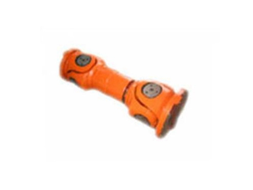
-
product name:
-
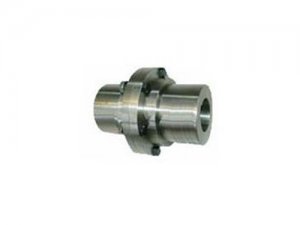
product description:SWCBF Standard Telescopic Flange Coupling Purpose: Used to connect two shafts (driving shaft and driven shaft) in different mechanisms to make them common..
-
Related tags:
Product Details
SWCBF standard telescopic flange coupling due to various reasons makes its center of mass or inertial main axis do not coincide with the axis of rotation, and it will produce unbalanced centrifugal inertial force, centrifugal inertial couple force and dynamic deflection (vibration shape) during operation. , Known as the unbalance phenomenon of the rotor, this unbalance phenomenon will inevitably cause the vibration of the shaft system, thereby affecting the normal operation and service life of the machine, so it should be paid attention to.The degree of unbalance (unbalance U) is usually expressed by the product mr of the mass m of the rotor and the distance r from the center of mass to the axis of rotation of the rotor, which is called the product of mass diameter.It is also expressed by the product of mass diameter per unit mass, called eccentricity (not geometrically eccentric.) The product of mass diameter mr is a relative quantity related to the mass of the rotor, while the eccentricity e is independent of the mass of the rotor. the amount.The former is relatively intuitive, and is often used for specific balancing operations of a given rotor. The latter is used to measure the pros and cons of the rotor balance or to detect the balance accuracy. The balance grade standard of the coupling is evaluated by e.For a flexible rotor, use the mode eccentricity (the nth mode) en=Un/mn, and Un and mn are the nth mode and the first mode quality respectively.
SWCBF Standard Telescopic Flange Coupling Purpose: Used to connect two shafts (active shaft and driven shaft) in different mechanisms to make them rotate together to transmit torque mechanical parts. In high-speed and heavy-duty power transmission, Some couplings also have the function of buffering, damping and improving the dynamic performance of the shafting.The coupling is composed of two halves, which are respectively connected with the driving shaft and the driven shaft.The general power machine is mostly connected with the working machine by means of a coupling.
Coupling selection requirements:
According to the characteristics of the model and the operation of the system, select the appropriate coupling form:
1. Torque
The torque of the coupling should be twice the transmission torque. For example, if the transmission torque value is 5 (NM), a coupling with a torque value of 10 (N.,) should be selected. The material should be rigid torque.
2. Flexible/rigid
Flexible couplings can absorb parallel deviation, angular bottom deviation, and axial displacement. High-rigidity couplings do not, so the accuracy of the shaft end is very high.
3. Applicable occasions-high and low temperature. Acid...
Choose the material of the coupling, whether it can load acid, high and low temperature occasions.
4. With or without backlash
5. Insulation
6. Be vibrating
7. Tolerable speed
8. Has the ability to protect the machine
9. Is the aperture range applicable?
| Model | Project | SWC 160 | SWC 180 | SWC 200 | SWC 225 | SWC 250 | SWC 265 | SWC 285 | SWC 315 | SWC 350 | SWC 390 | SWC 440 | SWC 490 | SWC 550 | SWC 620 |
| A type | L | 740 | 800 | 900 | 1000 | 1060 | 1120 | 1270 | 1390 | 1520 | 1530 | 1690 | 1850 | 2060 | 2280 |
| Lv | 100 | 100 | 120 | 140 | 140 | 140 | 140 | 140 | 150 | 170 | 190 | 190 | 240 | 250 | |
| m(kg) | 65 | 83 | 115 | 152 | 219 | 260 | 311 | 432 | 610 | 804 | 1122 | 1468 | 2154 | 2830 | |
| Type B | L | 480 | 530 | 590 | 640 | 730 | 790 | 840 | 930 | 1000 | 1010 | 1130 | 1240 | 1400 | 1520 |
| m(kg) | 44 | 60 | 85 | 110 | 160 | 180 | 226 | 320 | 440 | 590 | 820 | 1090 | 1560 | 2100 | |
| Type C | L | 380 | 420 | 440 | 500 | 560 | 600 | 640 | 720 | 780 | 860 | 960 | 1080 | 1220 | 1560 |
| m(kg) | 35 | 48 | 66 | 90 | 130 | 160 | 189 | 270 | 355 | 510 | 690 | 970 | 1330 | 1865 | |
| Type D | L | 520 | 580 | 620 | 690 | 760 | 810 | 860 | 970 | 1030 | 1120 | 1230 | 1360 | 1550 | 1720 |
| m(kg) | 48 | 65 | 90 | 120 | 173 | 220 | 250 | 355 | 485 | 665 | 920 | 1240 | 1765 | 2390 | |
| And 型 | L | 800 | 850 | 940 | 1050 | 1120 | 1180 | 1320 | 1440 | 1550 | 1710 | 1880 | 2050 | 2310 | 2540 |
| LV | 100 | 100 | 120 | 140 | 140 | 140 | 140 | 140 | 150 | 170 | 190 | 190 | 240 | 250 | |
| m(kg) | 70 | 92 | 126 | 168 | 238 | 280 | 340 | 472 | 660 | 886 | 1230 | 1625 | 2368 | 3135 | |
| Tn | kN*m | 18 | 25 | 35.5 | 40 | 63 | 80 | 90 | 125 | 180 | 250 | 355 | 500 | 710 | 1000 |
| Tf | kN*m | 9 | 12.5 | 18 | 20 | 31.5 | 40 | 45 | 63 | 90 | 125 | 180 | 250 | 355 | 500 |
| β | ° | 15 | 15 | 15 | 15 | 15 | 15 | 15 | 15 | 15 | 15 | 15 | 15 | 15 | 15 |
| D | 160 | 180 | 200 | 225 | 250 | 265 | 285 | 315 | 350 | 390 | 440 | 490 | 550 | 620 | |
| Df | 160 | 180 | 200 | 225 | 250 | 265 | 285 | 315 | 350 | 390 | 440 | 490 | 550 | 620 | |
| D1 | 137 | 155 | 170 | 196 | 218 | 233 | 245 | 280 | 310 | 345 | 390 | 435 | 492 | 555 | |
| D2(H9) | 100 | 105 | 120 | 135 | 150 | 160 | 170 | 185 | 210 | 235 | 255 | 275 | 320 | 380 | |
| D3×δ | 114 × 11 | 127 × 12 | 146 × 13 | 159 × 12 | 180 × 14 | 194 × 15 | 203 × 16 | 219 × 19 | 245 × 22 | 273 × 25 | 325 × 25 | 351 × 30 | 402 × 32 | 426 × 40 | |
| Lm | 95 | 105 | 110 | 125 | 140 | 150 | 160 | 180 | 195 | 215 | 240 | 270 | 305 | 340 | |
| K | 16 | 17 | 18 | 20 | 25 | 25 | 27 | 32 | 35 | 40 | 42 | 47 | 50 | 55 | |
| t | 4 | 5 | 5 | 5 | 6 | 6 | 7 | 8 | 8 | 8 | 10 | 12 | 12 | 12 | |
| n | 8 | 8 | 8 | 8 | 8 | 8 | 8 | 10 | 10 | 10 | 16 | 16 | 16 | 16 | |
| d | 15 | 17 | 17 | 17 | 19 | 19 | 21 | 23 | 23 | 25 | 28 | 31 | 31 | 38 | |
| b | 20 | 24 | 28 | 32 | 40 | 40 | 40 | 40 | 50 | 70 | 80 | 90 | 100 | 100 | |
| g | 6.0 | 7.0 | 8.0 | 9.0 | 12.5 | 12.5 | 15.0 | 15.0 | 16.0 | 18.0 | 20.0 | 22.5 | 22.5 | 25 | |
| mL | kg | 2.80 | 3.40 | 4.26 | 4.35 | 5.73 | 6.62 | 7.38 | 9.37 | 12.10 | 15.29 | 18.50 | 23.75 | 29.12 | 38.08 |
| Flange bolt | specification | M14 | M16 | M16 | M16 | M18 | M18 | M20 | M22 | M22 | M24 | M27 | M30 | M30 | M36 |
| Tightening torque (N*m) | 180 | 270 | 270 | 270 | 372 | 372 | 526 | 710 | 710 | 906 | 1340 | 1820 | 1820 | 3170 | |
Company News
News

-
 Coupling manufacturer's diaphragm coupling link device
How many sets of diaphragms (stainless steel thin plate) of the diaphragm coupling of the coupling manufacturer are interwoven with bolts...
Coupling manufacturer's diaphragm coupling link device
How many sets of diaphragms (stainless steel thin plate) of the diaphragm coupling of the coupling manufacturer are interwoven with bolts... Causes of coupling failures of coupling manufacturers
The characteristics of the sprocket coupling: the chain coupling has a simple structure, easy to assemble and disassemble, and there is no need to move when disassembling...
Causes of coupling failures of coupling manufacturers
The characteristics of the sprocket coupling: the chain coupling has a simple structure, easy to assemble and disassemble, and there is no need to move when disassembling... Shaft manufacturers analyze various types of coupling lubrication maintenance methods
Good lubrication of the coupling is to operate, it is a method to slow down the wear, and it is also an important way to improve the life of the coupling...
Shaft manufacturers analyze various types of coupling lubrication maintenance methods
Good lubrication of the coupling is to operate, it is a method to slow down the wear, and it is also an important way to improve the life of the coupling... Common failures of couplings
In the daily use of toothed couplings, the coupling manufacturer will show you that the following...
Common failures of couplings
In the daily use of toothed couplings, the coupling manufacturer will show you that the following... -
 Disassembly tool and maintenance of pin coupling
The pin coupling is used to drive the starter gearbox, starter generator and exciter.Pin coupling...
Disassembly tool and maintenance of pin coupling
The pin coupling is used to drive the starter gearbox, starter generator and exciter.Pin coupling...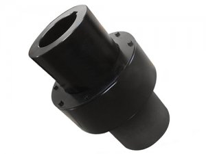 Technical advantages of flexible diaphragm coupling
1. Dry couplings, non-lubricated flexible diaphragm couplings rely on metal diaphragms to transmit torque and absorb...
Technical advantages of flexible diaphragm coupling
1. Dry couplings, non-lubricated flexible diaphragm couplings rely on metal diaphragms to transmit torque and absorb... Coupling requirements and optimized design structure
The torque transmission of the coupling is mainly to set the nominal torque requirement of the transmission system.When the torque transmission element...
Coupling requirements and optimized design structure
The torque transmission of the coupling is mainly to set the nominal torque requirement of the transmission system.When the torque transmission element... Advantages of universal coupling
What are the advantages of universal couplings and how to choose universal couplings?Coupling manufacturer for you to introduce...
Advantages of universal coupling
What are the advantages of universal couplings and how to choose universal couplings?Coupling manufacturer for you to introduce... -
 Eight factors for choosing a coupling
There are many types, types and specifications of couplings.In the correct understanding of the concept of varieties, varieties and specifications...
Eight factors for choosing a coupling
There are many types, types and specifications of couplings.In the correct understanding of the concept of varieties, varieties and specifications... Coupling efficiency
Coupling manufacturer Hangzhou Hengli Transmission Equipment Co., Ltd. introduces you the efficiency of the coupling: ...
Coupling efficiency
Coupling manufacturer Hangzhou Hengli Transmission Equipment Co., Ltd. introduces you the efficiency of the coupling: ... Causes of pin burning caused by elastic sleeve pin coupling
The coupling manufacturer will introduce to you: the reason for the pin burning caused by the elastic sleeve pin coupling. In recent years, small...
Causes of pin burning caused by elastic sleeve pin coupling
The coupling manufacturer will introduce to you: the reason for the pin burning caused by the elastic sleeve pin coupling. In recent years, small... How to use the coupling safely?
Normal use of the coupling can improve work efficiency, so what should we pay attention to when using it...
How to use the coupling safely?
Normal use of the coupling can improve work efficiency, so what should we pay attention to when using it...
Copyright © 2017-2018 Hengli Transmission All Right Reserved.